

Recommended drive circuits and selection of driving conditions
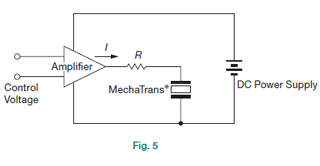
1. In case of Analog drive circuits; refer to Fig.5
The current I [Ampere] to the amplifier is calculated by the equation (2), and it should be a key factor for amplifier selection.
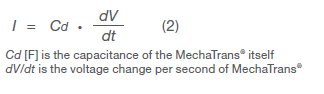
As the equation (2) does not include the current to the mechanical system, it is recommended to measure the current in prior to selection of the drive circuit.
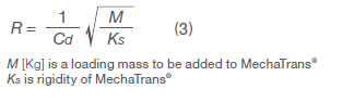
In order to get an optimum damping factor, the resistance R [Ohm] between the amplifier and MechaTrans® is calculated by the equation (3).
2. In case of digital drive circuits; refer to Fig.6 & 7
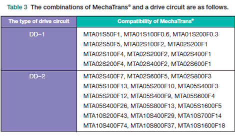
Combination both MechaTrans® and a drive circuit is shown on the Table3.
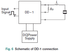
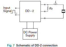
When a step voltage is supplied to MechaTrans® on the digital drive circuit, a large peak current flows both at the step-up point and at the step-down point because of the capacitive device. In order to avoid the peak current, it is necessary to add a resistance R or an inductance L between the drive circuit and MechaTrans®.
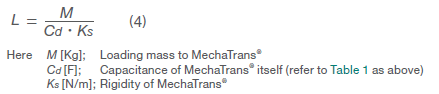
It is recommended to add L in stead of R if a large kinetic energy is required for MechaTrans®. The value of the L should be obtained by equation (4) by harmonizing the resonance frequency of the drive circuit with the mechanical resonance frequency.
Note:
Even though L has been decided, a saturation problem may happen due to the coil core material and the air gap.
In that case, please contact us to design and produce the optimum coil.
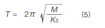
If a stop motion every input pulse voltage is required, the input pulse signal time T [sec] should be determined by the equation (5).
The optimum Rd value on Fig. 6 and 7 can be obtained by actual experiment basis, and in fact, it is expected to be between a few [Ω] to 200[Ω].
It is also important to select the resistance with enough wattage because the driving energy on the circuit is almost consumed by both the coil resistance and Rd.
If a slower motion is required for MechaTrans®, another resistance Rs is possible to use in stead of the L and it is also possible to minimize the physical overshooting amount by controlling the input signal. It is also required to contact us when MechaTrans® is used under dynamic conditions.
Note:
In case of the L selection, the pulse voltage must be less than 80 [V] because almost twice of the base voltage may be supplied to MechaTrans® as the peak voltage.
In case of the Rs selection, the pulse voltage must be less than 130 [V] because the higher peak voltage than the base voltage may be supplied to MechaTrans®.