


Piezo Assist Motor *
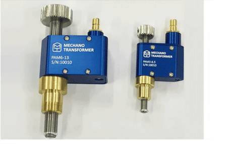
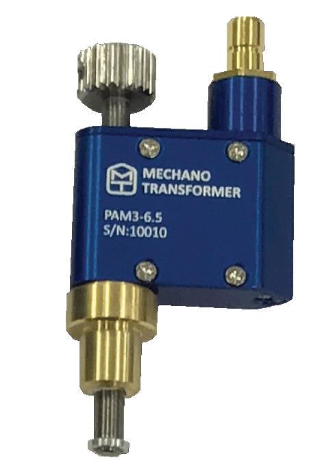
Piezo Assist Motor(PAM3-6.5 and PAM6-13)
- Assist Motor is compact in size, and designed to have a high output force up to around 13N for PAM3-6.5 and around 29N for PAM6-13.
- The output displacement is 6.5mm for PAM3-6.5 and 13mm for PAM6-13. The high displacement resolution is below 25nm~30nm while the travel velocity is above 1.5m/s.
- The Piezo Assist Motor is designed user friendly for industrial, scientific research applications.
- Applications include Microscope scanning, High resolution microscope, Biotechnology, Measurement technology, High speed throughput microscope, Mask/ Wafer positioning, Interferometer shape measurement and Micromanipulation.
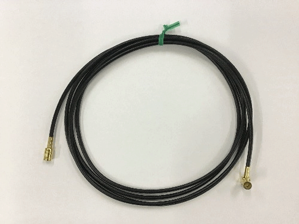
- Please use the designated Piezo Assist Motor Controller (PAMC-104)to drive the Piezo Assist Motor. A software and cable (2m) is attached to Piezo Assist Motor.
* “Piezo Assist” and “PiezoAssist” are registered trademarks of Mechano Transformer Corporation.
Driving example (reference)
PAM3-6.5 (weight 1.5kg played at about 100x speed)
PAM6-13 (Weight 3kg played at about 1,000x speed)
- Microscope scanning
- High resolution microscope
- Biotechnology
- Measurement technology
- High speed throughput microscope
- Mask/ Wafer positioning
- Interferometer shape measurement
- Micromanipulation
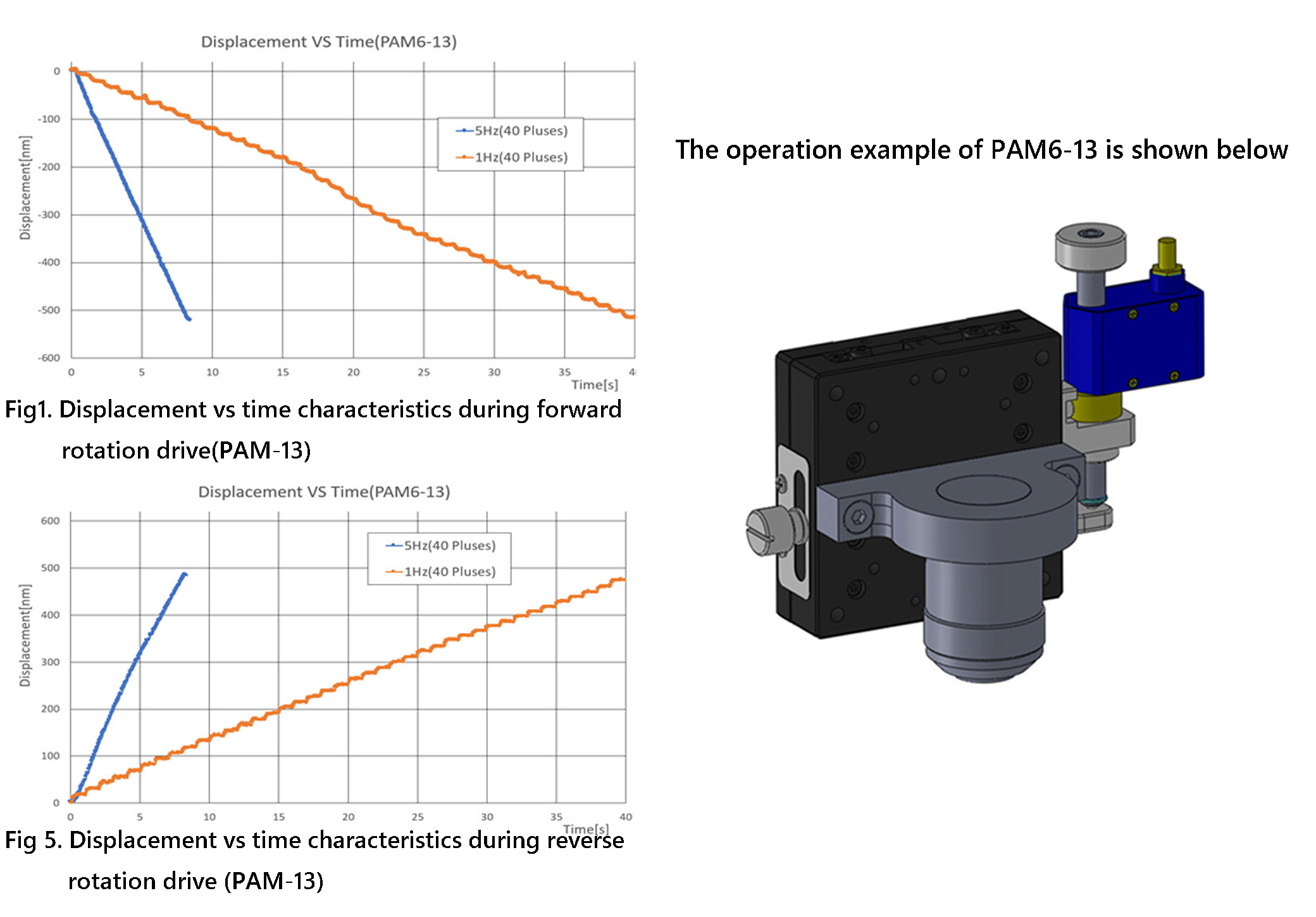
- At 1Hz, the displacement is stepped at 10~16nm/pulse, and the displacement is smooth at 5Hz.
- The displacement for 40pulses is 480nm (average 12nm/pulse) in forward rotation for both 1Hz and 5Hz. They are 520nm(average 13nm/pulse) in reverse rotation.
- Ultra-fine resolution in Nanometer
- Holds position even when power is not supplied
- Movable angle range is ±3.5°(≒ ± 61mrad )
- 1.6 μrad Ultra-precise adjustment by ( Over 70,000 steps)
- A piezoelectric actuator does not know its own absolute position.
- Do not touch the piezo-assisted motor as high voltage is present during operation.
- Do not disassemble the piezo-assisted motor.
- Do not use the piezo-assisted motor near flammable materials or in humid locations.
- Do not apply power to the controller or piezo-assisted motor after subjecting them to shock.
- When in operation, the piezo-assisted motor emits a high-pitched noise.
- higher resolution to below 30 nanometers
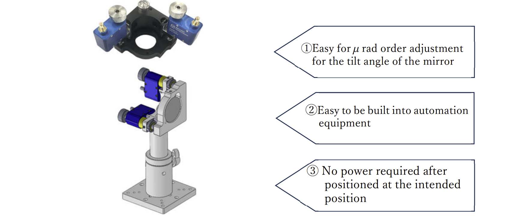
- After positioning, the intended position can be maintained without power supply
- from manual stage adjustment to electrical controlled precision stages
- Easily realize the automation of your equipment
- Easily achieves nanometer order precision of your equipment
- Maintain at adjusted position even without power supply
- Easily replaceable with micrometer head
- Easily visualize the amount of movement by attaching an external sensor
| Product | Price [yen] | |
|---|---|---|
| PAM3-6.5 | Piezo Assist Motor, Travel range 6.5mm, Minimum Movement 30nm, Mounting Part φ6 shank | 88,000 |
| PAM6-13 | Piezo Assist Motor, Travel range 13mm, Minimum Movement 25nm, Mounting Part φ95 shank | 77,000 |
| PAMC-104 | Piezo Assist Motor Controller, Driving Axis 4, RS232C Interface | 132,000 |
| PAMC-100 | Piezo Assist Motor Controller(remote control) | 55,000 |
| PAMC-204 | Piezo Assist Motor Controller, Driving Axis 4, RS485 Interface, usb | 176,000 |
| Tip shape | Travel range | Shank diameter | Anodization process | Controller | Drawing Plan (PDF) | Drawing Plan (.step) | |
|---|---|---|---|---|---|---|---|
| PAM6-13 | Flat | ±6.5mm | φ9.5 (M9.5 x 0.5) | Yes | PAMC-104/ PAMC-204 | A111 | link |
| PAM6-13R | R Type | ±6.5mm | φ9.5 (M9.5 x 0.5) | Yes | PAMC-104/PAMC-204 | A112 | link |
| PAM6-13R-C | R Type | ±3mm | φ9.5 (M9.5 x 0.5) | Yes | PAMC-104/ PAMC-204 | A110 | link |
| PAM6-13R-C2 | R Type | ±4mm | φ9.5 (M9.5 x 0.5) | Yes | PAMC-104/ PAMC-204 | A114 | link |
| PAM6-13R-C3 | R Type | ±6.5mm | φ9.5 (M9.5 x 0.5) | Yes | PAMC-104/ PAMC-204 | A115 | link |
| Tip shape | Travel range | Shank diameter | Anodization process | Controller | Drawing Plan (PDF) | Drawing Plan (.step) | |
|---|---|---|---|---|---|---|---|
| PAM6-13N | Flat | ±6.5mm | φ9.5 (M9.5 x 0.5) | No | PAMC-104/ PAMC-204 | A111 | link |
| PAM6-13RN | R Type | ±6.5mm | φ9.5 (M9.5 x 0.5) | No | PAMC-104/PAMC-204 | A112 | link |
| PAM6-13R-CN | R Type | ±3mm | φ9.5 (M9.5 x 0.5) | No | PAMC-104/ PAMC-204 | A110 | link |
| PAM6-13R-C2N | R Type | ±4mm | φ9.5 (M9.5 x 0.5) | No | PAMC-104/ PAMC-204 | A114 | link |
| PAM6-13R-C3N | R Type | ±6.5mm | φ9.5 (M9.5 x 0.5) | No | PAMC-104/ PAMC-204 | A115 | link |
| Tip shape | Travel range | Shank diameter | Anodization process | Controller | Drawing Plan (PDF) | Drawing Plan (.step) | ||||||||
|---|---|---|---|---|---|---|---|---|---|---|---|---|---|---|
| PAM3-6.5 | Flat | ±3mm | φ6 | Yes | PAMC-104/ PAMC-204 | A105 | link | |||||||
| PAM3-6.5R | R Type | ±3mm | φ6 | Yes | PAMC-104/ PAMC-204 | A104 | link | |||||||
| PAM3-6.5R-C1 | R Type | ±(3mm±0.2) | φ5 | Yes | PAMC-104/ PAMC-204 | A106 | link |
| Tip shape | Travel range | Shank diameter | Anodization process | Controller | Drawing Plan (PDF) | Drawing Plan (.step) | |
|---|---|---|---|---|---|---|---|
| PAM3-6.5N | Flat | ±3mm | φ6 | No | PAMC-104/ PAMC-204 | A105 | link |
| PAM3-6.5RN | R Type | ±3mm | φ6 | No | PAMC-104/ PAMC-204 | A104 | link |
| PAM3-6.5R-C1N | R Type | ±(3mm±0.2) | φ5 | No | PAMC-104/ PAMC-204 | A106 | link |
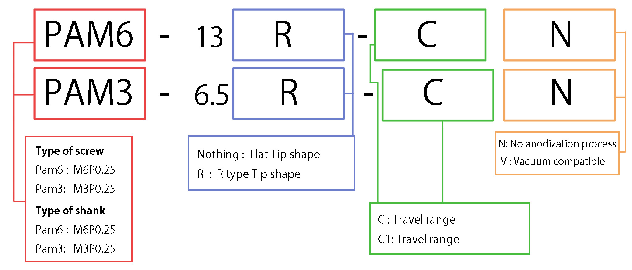
# PAM's product code:
Piezo Assist Motor Operating Principal
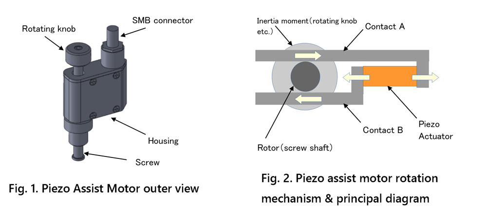
Piezo assist motor rotates based on the inertial rotation mechanism inside the housing. This generates thrust and displacement in the direction of the screw shaft. As shown in Fig. 2, the inertial rotation mechanism principal diagram, the screw shaft work as a rotor. The screw shaft is connected to the moment of inertia (rotary knob, etc.). The screw shaft is hold by the contactor with stat-ic friction force. Therefore, no power consumption is needed to maintain the po-sition. When the piezoelectric actuator extends as shown in Fig. 2, contacts A and B move at an opposite direction to each other. An acceleration at contact A and B is created intentionally. The acceleration will take over the static fric-tion and generate a slippage between rotor and contact. The slippage resulted a rotational motion of the screw shaft. As a result, the screw shaft is moved in a thrust direction.
Piezo Assist Motor Catalogue >> Link
Specifications & Dimension
| Product | PAM6-13 | PAM6-13R | PAM6-13R-C | PAM6-13R-C2 | PAM6-13N | PAM6-13RN | PAM6-13R-CN | PAM6-13R-C1N | PAM3-6.5 | PAM3-6.5R | PAM3-6.5R-C1 | PAM3-6.5N | PAM3-6 | PAM3-6.5R-C1N |
|---|---|---|---|---|---|---|---|---|---|---|---|---|---|---|
| Minimum Movement (nm) | 25 below | 25 below | 25 below | 25 below | 25 below | 25 below | 25 below | 25 below | 30 below | 30 below | 30 below | 30 below | 30 below | 30 below |
| Maximum load capacity(N) | 29.4 Above | 29.4 Above | 29.4 Above | 29.4 Above | 29.4 Above | 29.4 Above | 29.4 Above | 29.4 Above | 13 Above | 13 Above | 13 Above | 13 Above | 13 Above | 13 Above |
| Maximum Drive Frequency(kHz) | 1.5 | 1.5 | 1.5 | 1.5 | 1.5 | 1.5 | 1.5 | 1.5 | 1.5 | 1.5 | 1.5 | 1.5 | 1.5 | 1.5 |
| Maximum Speed(mm/min) | 1.5 Above | 1.5 Above | 1.5 Above | 1.5 Above | 1.5 Above | 1.5 Above | 1.5 Above | 1.5 Above | 1.5 Above | 1.5 Above | 1.5 Above | 1.5 Above | 1.5 Above | 1.5 Above |
| Travel Range(mm) | 13 Above( Maximum 18) | 13 Above(Maximum 18) | 5 Above(Maximum 7) | 6 Above(Maximum 8) | 13 Above(Maximum 18) | 13 Above(Maximum 18) | 5 Above(Maximum 7) | 6 Above(Maximum 8) | 6.5 Above(Maximum 9) | 6.5 Above(Maximum 9) | 4 Above(Maximum 6) | 6.5 Above(Maximum 9) | 6.5 Above(Maximum 9) | 4 Above(Maximum 6) |
| Mounting Part(mm) | M9.5x0.5 screw | M9.5x0.5 screw | M9.5x0.5 screw | φ9.5 Shank | M9.5x0.5 screw | M9.5x0.5 screw | M9.5x0.5 screw | φ9.5 Shank | φ6 Shank | φ6 Shank | φ5 Shank | φ6 Shank | φ6 Shank | φ5 Shank |
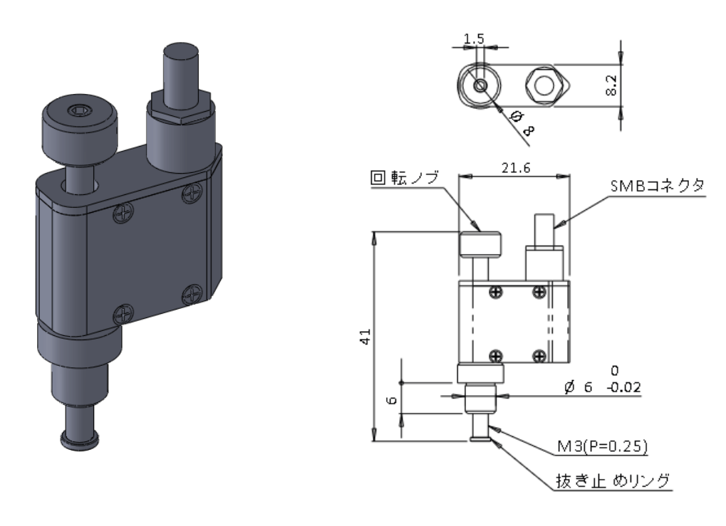
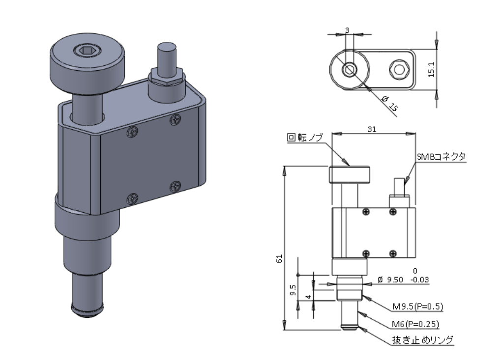
| Dimension(mm) | 61x32x15.1 | 63x32x15.1 | 52.5x32x15.1 | 47.5x32x15.1 | 61x32x15.1 | 63x32x15.1 | 52.5x32x15.1 | 47.5x32x15.1 | 41x21.6x8.2 | 43x21.6x8.2 | 37.2x21.6x7.2 | 41x21.6x8.2 | 43x21.6x8.2 | 37.2x21.6x7.2 |
| Operating temperature | 10~40℃ | 10~40℃ | 10~40℃ | 10~40℃ | 10~40℃ | 10~40℃ | 10~40℃ | 10~40℃ | 10~40℃ | 10~40℃ | 10~40℃ | 10~40℃ | 10~40℃ | 10~40℃ |
| Storage Temperature | 5~40℃ | 5~40℃ | 5~40℃ | 5~40℃ | 5~40℃ | 5~40℃ | 5~40℃ | 5~40℃ | 5~40℃ | 5~40℃ | 5~40℃ | 5~40℃ | 5~40℃ | 5~40℃ |
| Ambient Humidity | 10~80%RH(No condensation) | 10~80%RH(No condensation) | 10~80%RH(No condensation) | 10~80%RH(No condensation) | 10~80%RH(No condensation) | 10~80%RH(No condensation) | 10~80%RH(No condensation) | 10~80%RH(No condensation) | 10~80%RH(No condensation) | 10~80%RH(No condensation) | 10~80%RH(No condensation) | 10~80%RH(No condensation) | 10~80%RH(No condensation) | 10~80%RH(No condensation) |
| Connector | SMB Connector | SMB Connector | SMB Connector | SMB Connector | SMB Connector | SMB Connector | SMB Connector | SMB Connector | SMB Connector | SMB Connector | SMB Connector | SMB Connector | SMB Connector | SMB Connector |
| life span | 1 billion above | 1 billion above | 1 billion above | 1 billion above | 1 billion above | 1 billion above | 1 billion above | 1 billion above | 1 billion above | 1 billion above | 1 billion above | 1 billion above | 1 billion above | 1 billion above |
| Mass(kg) | 0.05 | 0.05 | 0.05 | 0.05 | 0.05 | 0.05 | 0.05 | 0.05 | 0.02 | 0.02 | 0.02 | 0.02 | 0.02 | 0.02 |
| Price(yen) | 77,000 | 77,000 | 77,000 | 77,000 | 77,000 | 77,000 | 77,000 | 77,000 | 88,000 | 88,000 | 88,000 | 88,000 | 88,000 | 88,000 |
| User manual | Download | Download | Download | Download | Download | Download | Download | Download | Download | Download | Download | Download | Download | Download |
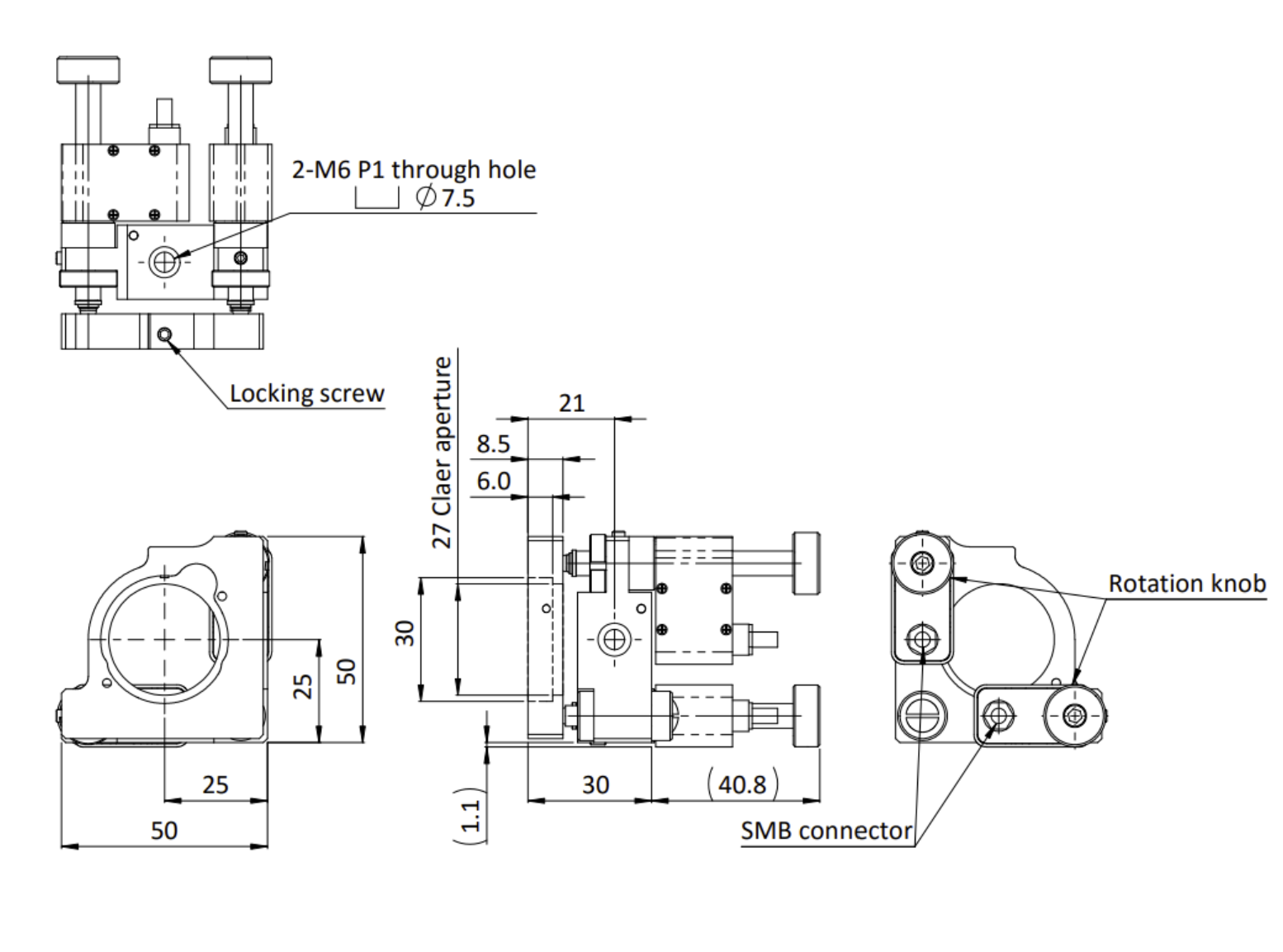
外形図(単位:mm)
PAM3-6.5
PAM6-13
Dedicated cable(2m)
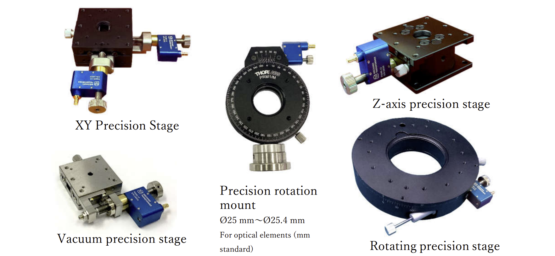
MTPAM-TSD-402SR
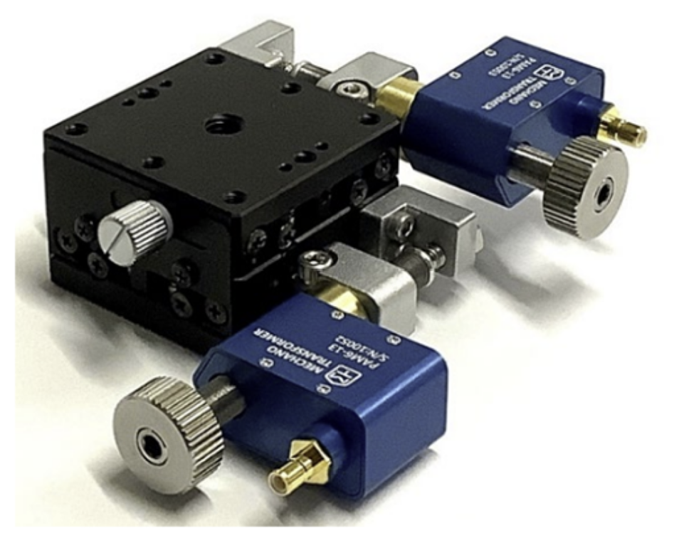
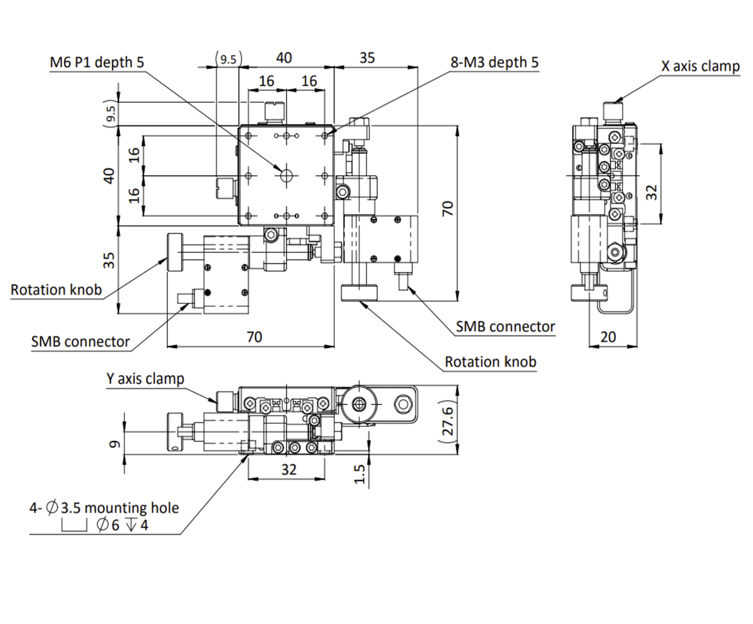
The Nano Alignment Stage Series is designed to construct an optical experimental system more quickly and easily. The MTPAM-TSD-402SR is an electrical driven XY axis stage which is ideal for positioning a load of 20kgf with resolution below 30nm. The optical experimental systems mentioned are mainly based on Michelson interferometer.
PDF Download 3D Model Download here
| Stage Size | 40×40mm |
|---|---|
| Piezo resolution | < 20nm |
| Moment Stiffness / Pitch | 0.5″/N・cm |
| Moment Stiffness / Yaw | 0.46″/N・cm |
| Moment Stiffness / Roll | 0.5″/N・cm |
| Guide Method | Extended Contact Ball Bearing Guide |
| Travel Accuracy / Pitch | 25" |
| Travel Accuracy / Yaw | 15" |
| Travel Accuracy / Straightness | 0.5μm |
| Running Parallelism | 12μm |
| Travel | ±6.5mm |
| Lead of Actuator | 0.25mm |
| Max. Moment Capacity / Pitch | 7.8N・m |
| Max. Moment Capacity / Yaw | 5.0N・m |
| Max. Moment Capacity / Roll | 7.8N・m |
| Weight | 0.41Kg |
| Primary material | Steel |
| Finish | Super black chrome/Blue Anodized |
| Parallelism | 30μm |
| Orthogonality | 10μm |
The Nano Alignment Stage Series is driven by Piezo Assist MotorⓇ. With Piezo Assist MotorⓇ, the nanometer order alignment can be easily realized. The stage can be electrically controlled or manually adjust. The backlash is smaller than the widely used manual stage.
MTPAM-TSD-602SR
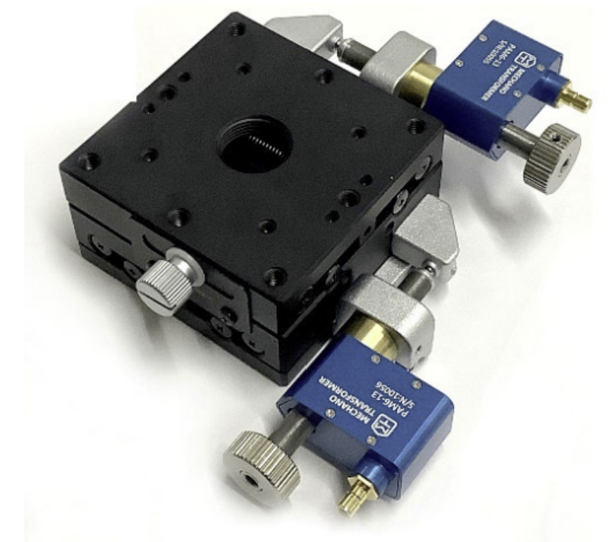
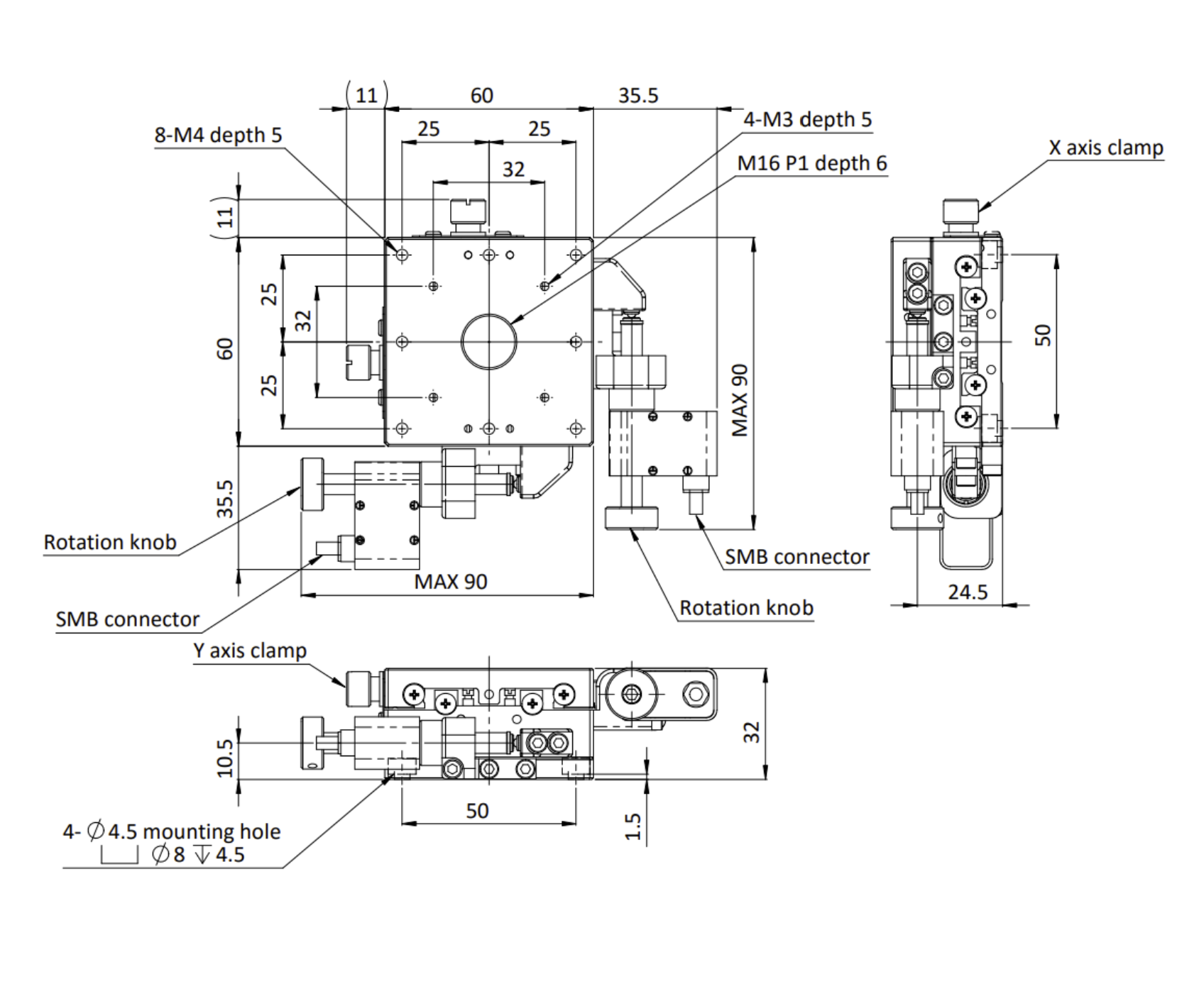
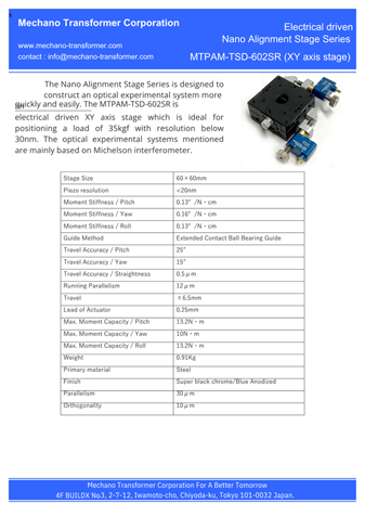
The Nano Alignment Stage Series is designed to construct an optical experimental system more quickly and easily. The MTPAM-TSD-602SR is an electrical driven XY axis stage which is ideal for positioning a load of 35kgf with resolution below 30nm. The optical experimental systems mentioned are mainly based on Michelson interferometer.
PDF Download 3D Model Download here
| Stage Size | 60×60mm |
|---|---|
| Piezo resolution | < 20nm |
| Moment Stiffness / Pitch | 0.31″/N・cm |
| Moment Stiffness / Yaw | 0.16″/N・cm |
| Moment Stiffness / Roll | 0.13″/N・cm |
| Guide Method | Extended Contact Ball Bearing Guide |
| Travel Accuracy / Pitch | 25" |
| Travel Accuracy / Yaw | 15" |
| Travel Accuracy / Straightness | 0.5μm |
| Running Parallelism | 12μm |
| Travel | ±6.5mm |
| Lead of Actuator | 0.25mm |
| Max. Moment Capacity / Pitch | 13.2N・m |
| Max. Moment Capacity / Yaw | 10N・m |
| Max. Moment Capacity / Roll | 13.2N・m |
| Weight | 0.91Kg |
| Primary material | Steel |
| Finish | Super black chrome/Blue Anodized |
| Parallelism | 30μm |
| Orthogonality | 10μm |
The Nano Alignment Stage Series is driven by Piezo Assist MotorⓇ. With Piezo Assist MotorⓇ, the nanometer order alignment can be easily realized. The stage can be electrically controlled or manually adjust. The backlash is smaller than the widely used manual stage.
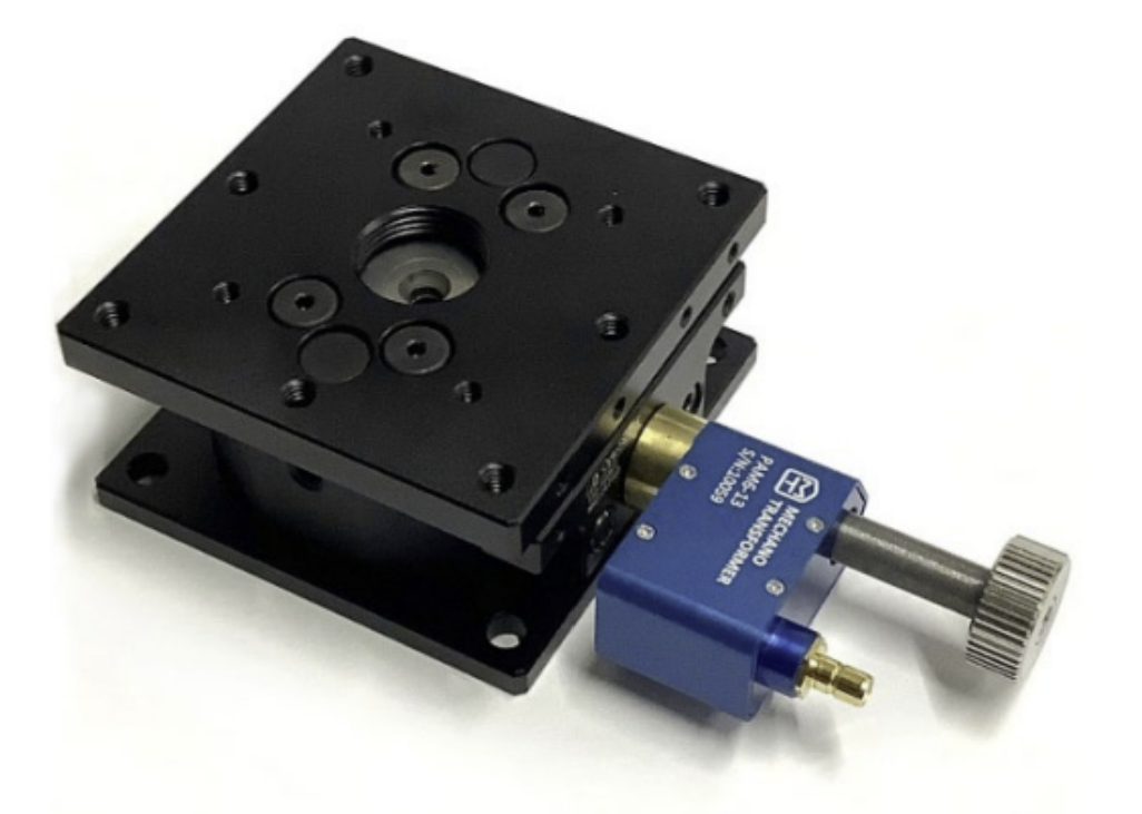
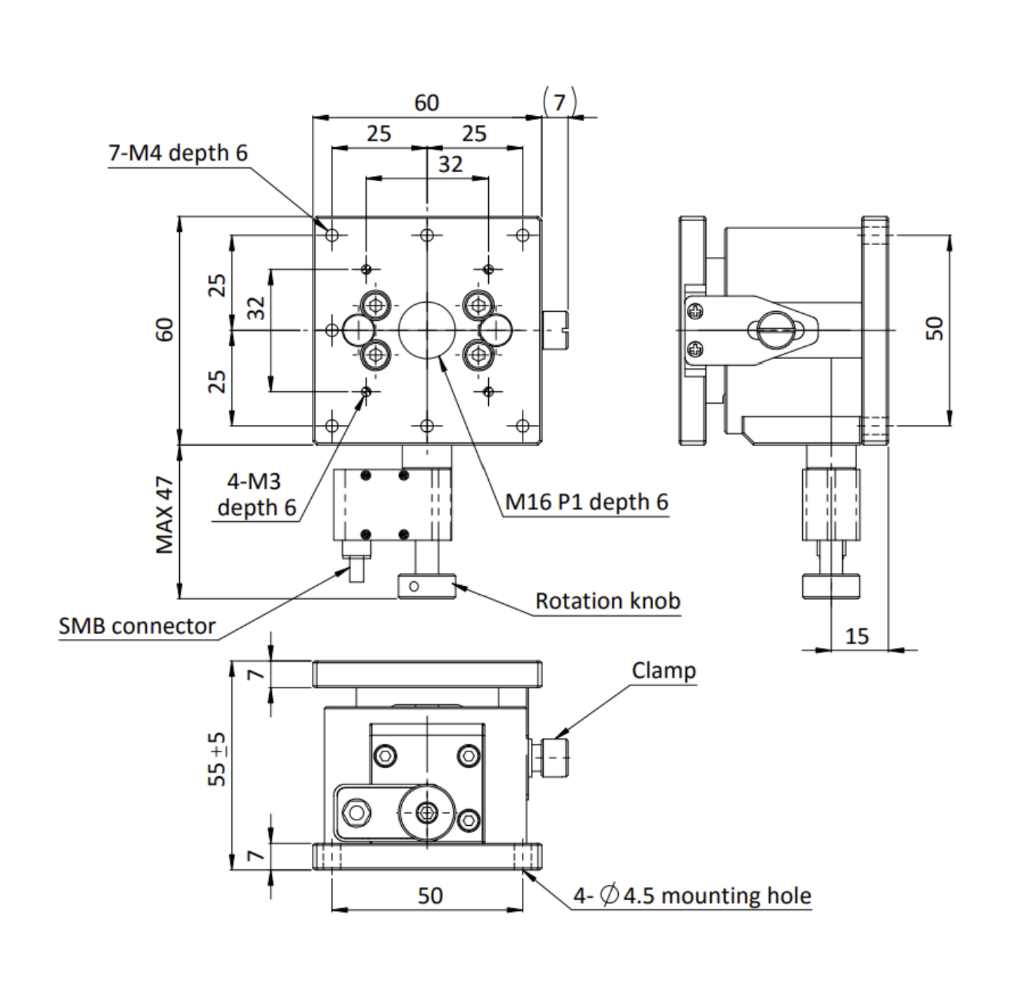
MTPAM-TSD-603
The Nano Alignment Stage Series is designed to construct an optical experimental system more quickly and easily. The MTPAM-TSD-603 is an electrical driven Z axis stage which is ideal for positioning a load of 15kgf with resolution below 30nm. The optical experimental systems mentioned are mainly based on Michelson interferometer.
PDF Download 3D Model Download here
| Stage Size | 60×60mm |
|---|---|
| Piezo resolution | 20nm |
| Moment Stiffness / Pitch | 0.41″/N・cm |
| Moment Stiffness / Yaw | - |
| Moment Stiffness / Roll | 0.41″/N・cm |
| Guide Method | Extended Contact Ball Bearing Guide |
| Travel Accuracy / Pitch | - |
| Travel Accuracy / Yaw | - |
| Travel Accuracy / Straightness | 2.5μm |
| Running Parallelism | 20μm |
| Travel | ±5mm |
| Lead of Actuator | 0.25mm |
| Max. Moment Capacity / Pitch | 6.9N・m |
| Max. Moment Capacity / Yaw | - |
| Max. Moment Capacity / Roll | 6.9N・m |
| Weight | 0.81Kg |
| Primary material | Steel |
| Finish | Black Matte/Blue Anodized |
| Parallelism | 80μm |
The Nano Alignment Stage Series is driven by Piezo Assist MotorⓇ. With Piezo Assist MotorⓇ, the nanometer order alignment can be easily realized. The stage can be electrically controlled or manually adjust. The backlash is smaller than the widely used manual stage.
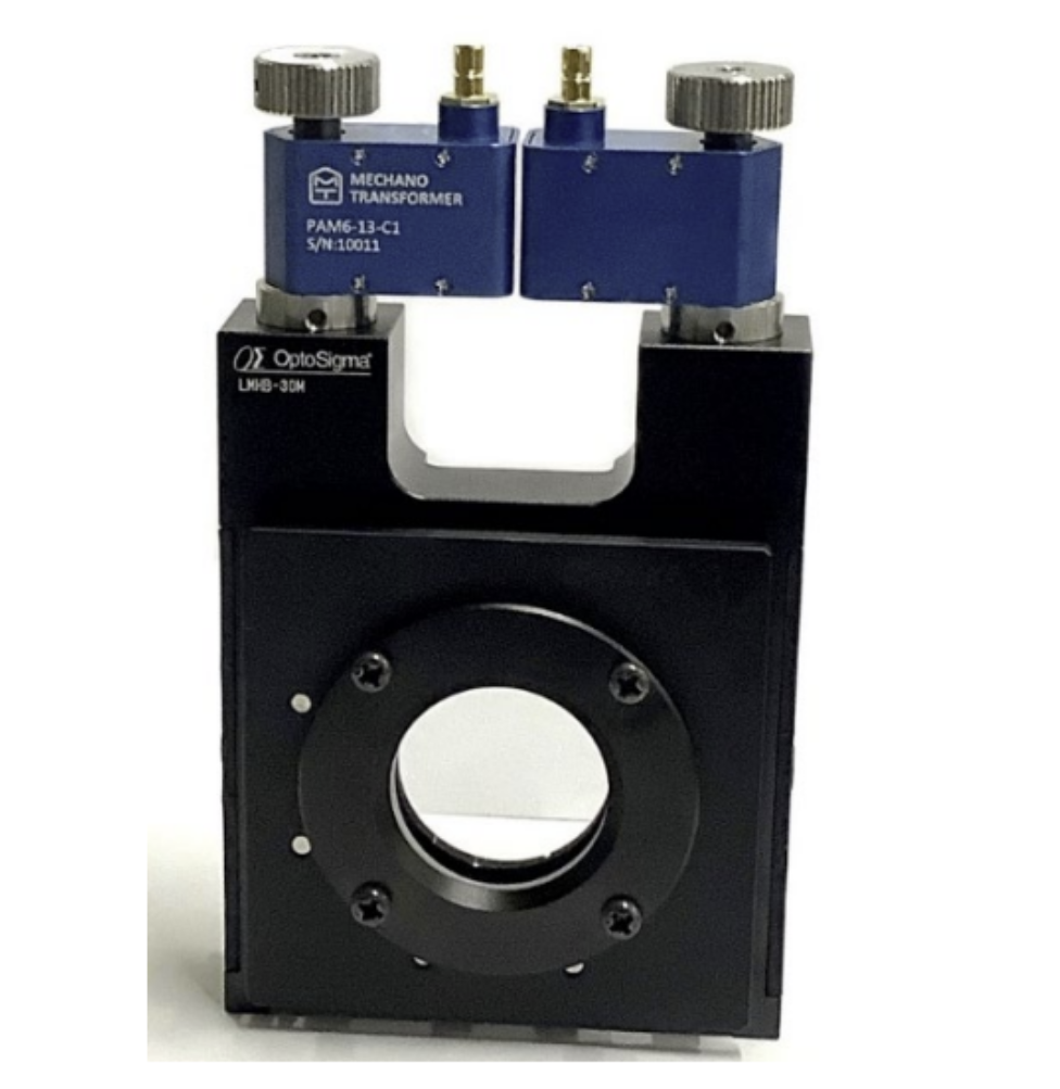
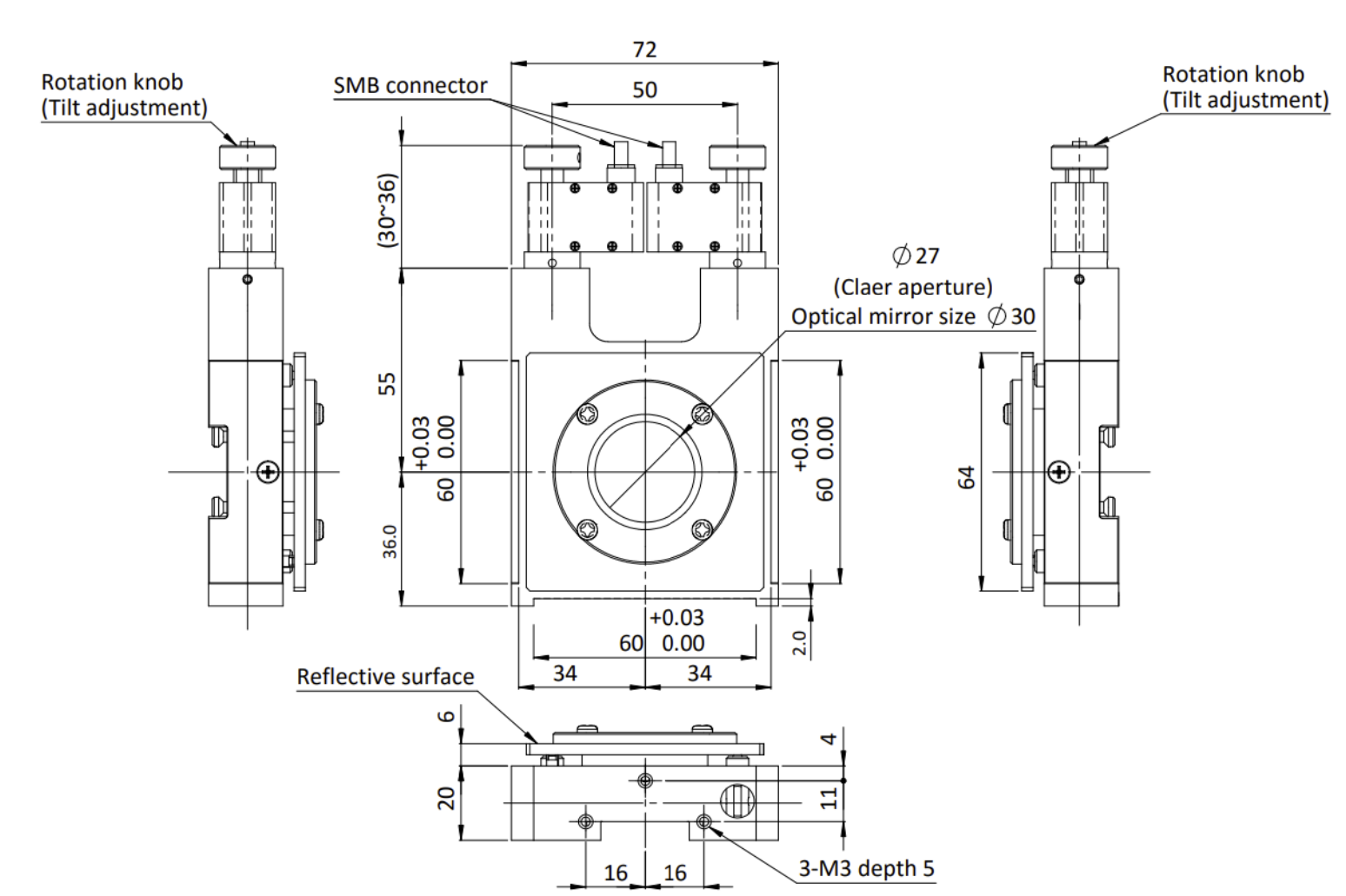
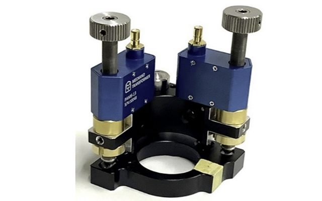
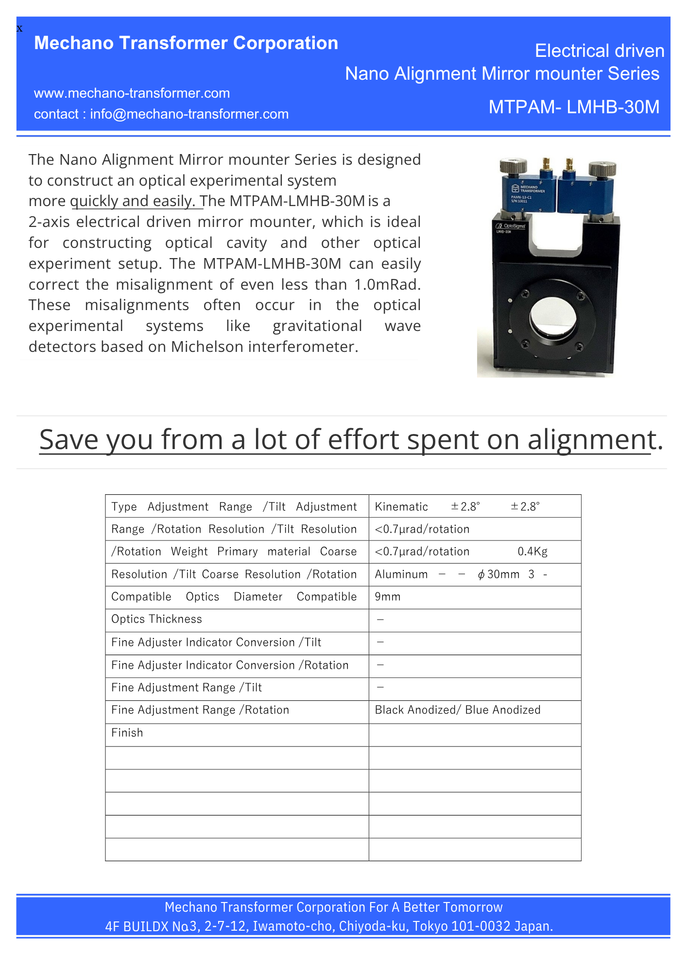
MTPAM-LMHB-30M
The Nano Alignment Mirror mounter Series is designed to construct an optical experimental system more quickly and easily. The MTPAM-LMHB-30M is a 2-axis electrical driven mirror mounter, which is ideal for constructing optical cavity and other optical experiment setup. The MTPAM-LMHB-30M can easily correct the misalignment of even less than 1.0mRad. These misalignments often occur in the optical experimental systems like gravitational wave detectors based on Michelson interferometer.
PDF Download 3D Model Download here
Save you from a lot of effort spent on alignment.
| Type | Kinematic |
|---|---|
| Adjustment Range /Tilt | ±2.8° |
| Adjustment Range /Rotation | ±2.8° |
| Resolution /Tilt | 0.7µrad/rotation |
| Resolution /Rotation | 0.7µrad/rotation |
| Weight | 0.4Kg |
| Primary material | Aluminum |
| Coarse Resolution /Tilt | - |
| Coarse Resolution /Rotation | - |
| Compatible Optics Diameter | φ30mm |
| Compatible Optics Thickness | 3 - 9mm |
| Fine Adjuster Indicator Conversion /Tilt | - |
| Fine Adjuster Indicator Conversion /Rotation | - |
| Fine Adjustment Range /Tilt | - |
| Fine Adjustment Range /Rotation | - |
| Finish | Black Anodized/Blue Anodized |
Automate your alignment with artificial intelligence like neural network or other algorithms.
The Nano Alignment Mirror mounter Series is driven by Piezo Assist MotorⓇ. With Piezo Assist MotorⓇ, the μ-1Rad order alignment can be easily realized. The mirror mounter can be electrically controlled. The backlash is smaller than the widely used manual mirror mounter.
MTPAM-MHG-MP30-NL
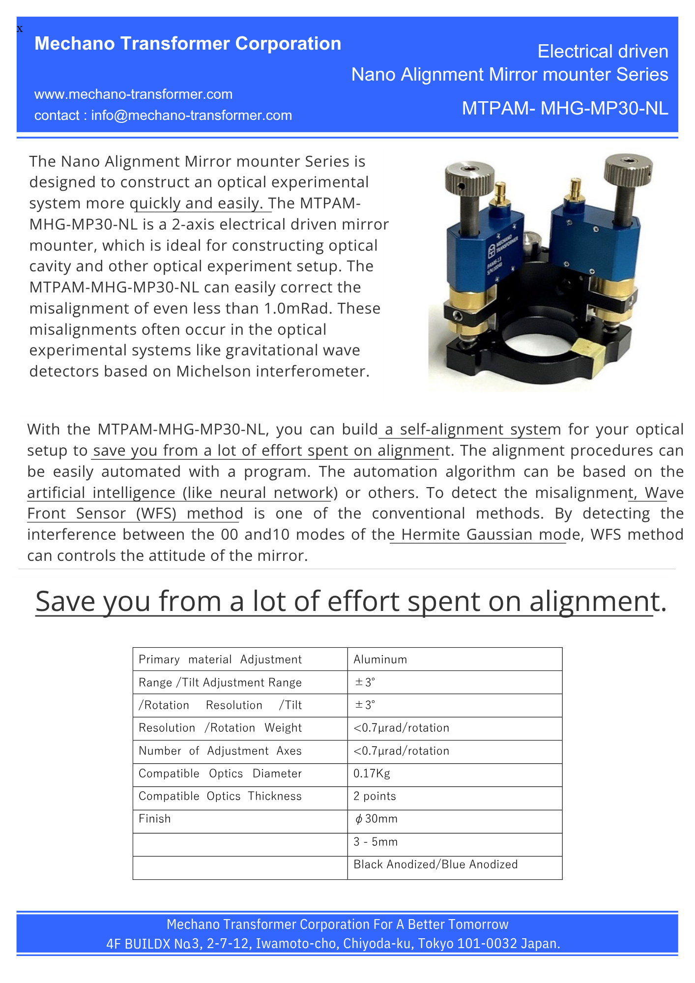
The Nano Alignment Mirror mounter Series is designed to construct an optical experimental system more quickly and easily. The MTPAM-MHG-MP30-NL is a 2-axis electrical driven mirror mounter, which is ideal for constructing optical cavity and other optical experiment setup. The MTPAM-MHG-MP30-NL can easily correct the misalignment of even less than 1.0mRad. These misalignments often occur in the optical experimental systems like gravitational wave detectors based on Michelson interferometer
With the MTPAM-MHG-MP30-NL, you can build a self-alignment system for your optical setup to save you from a lot of effort spent on alignment. The alignment procedures can be easily automated with a program. The automation algorithm can be based on the artificial intelligence (like neural network) or others. To detect the misalignment, Wave Front Sensor (WFS) method is one of the conventional methods. By detecting the interference between the 00 and10 modes of the Hermite Gaussian mode, WFS method can controls the attitude of the mirror.
PDF Download 3D Model Download here
Save you from a lot of effort spent on alignment.
| Primary material | Aluminum |
|---|---|
| Adjustment Range /Tilt | ±3° |
| Adjustment Range /Rotation | ±3° |
| Resolution /Tilt | 0.7µrad/rotation |
| Resolution /Rotation | 0.7µrad/rotation |
| Weight | 0.17Kg |
| Number of Adjustment Axes | 2 points |
| Compatible Optics Diameter | φ30mm |
| Compatible Optics Thickness | 3 - 5mm |
| Finish | Black Anodized/Blue Anodized |
| 2D Drawing | download |
| Solid Model |  |
The Nano Alignment Mirror mounter Series is driven by Piezo Assist MotorⓇ. With Piezo Assist MotorⓇ, the μ-1Rad order alignment can be easily realized. The mirror mounter can be electrically controlled. The backlash is smaller than the widely used manual mirror mounter.
Automate your alignment with artificial intelligence like neural network or other algorithms.
Application
(Application example of PAM6-13)To be attached to Piezo Assist Stage(Table Size 40x40mm, Table Size 60x60mm).
Piezo Assist Motor Operation Example
Fig.1 and Fig.2 show the displacement vs characteristics of the Piezo Assist Motor driven at 40 pulses with
drive frequencies of 1Hz and 5Hz. Fig.1 shows the data during forward
rotation, and Fig.2 shows data during
reverse rotation
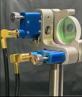
Application example of Piezo Assist Mirror (Angle Adjustment of Mirror Holder )
Driving test video (reference)
Installation & Precautions
4. Installation & Precautions
Controller and connection method
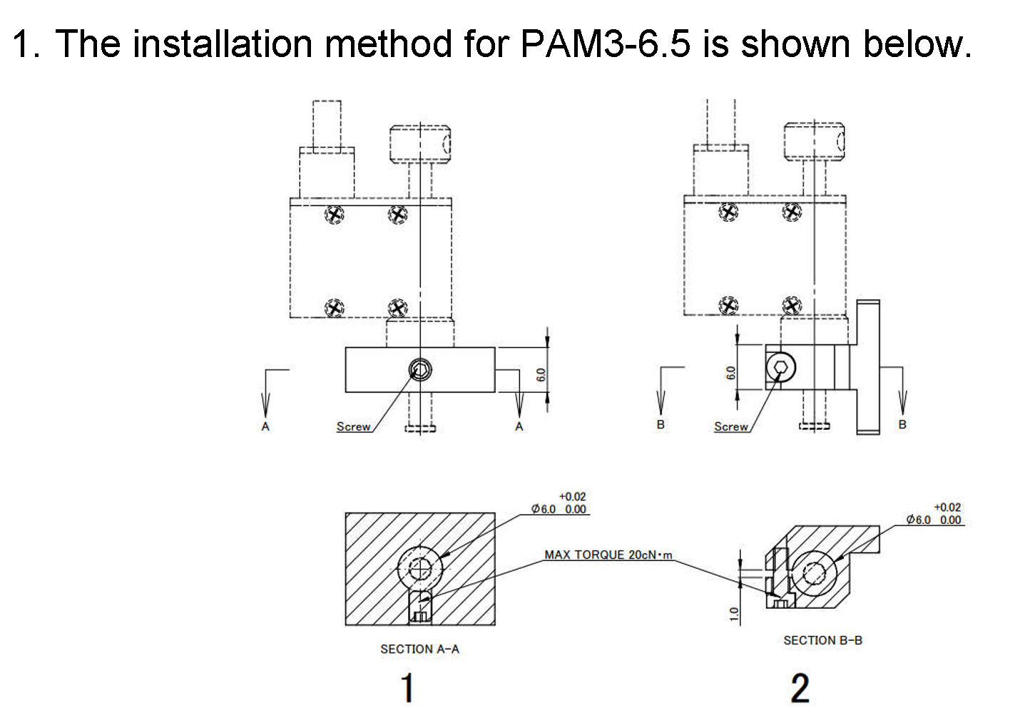
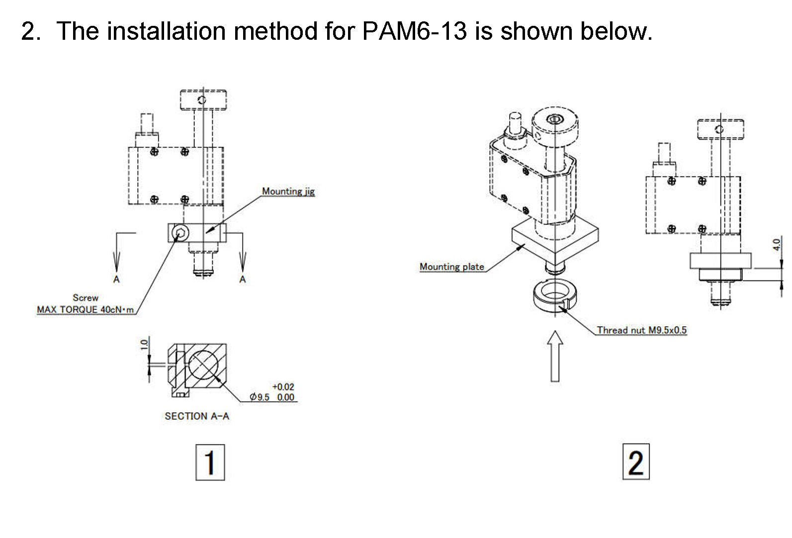
1. PAM3-6.5 or PAM6-13
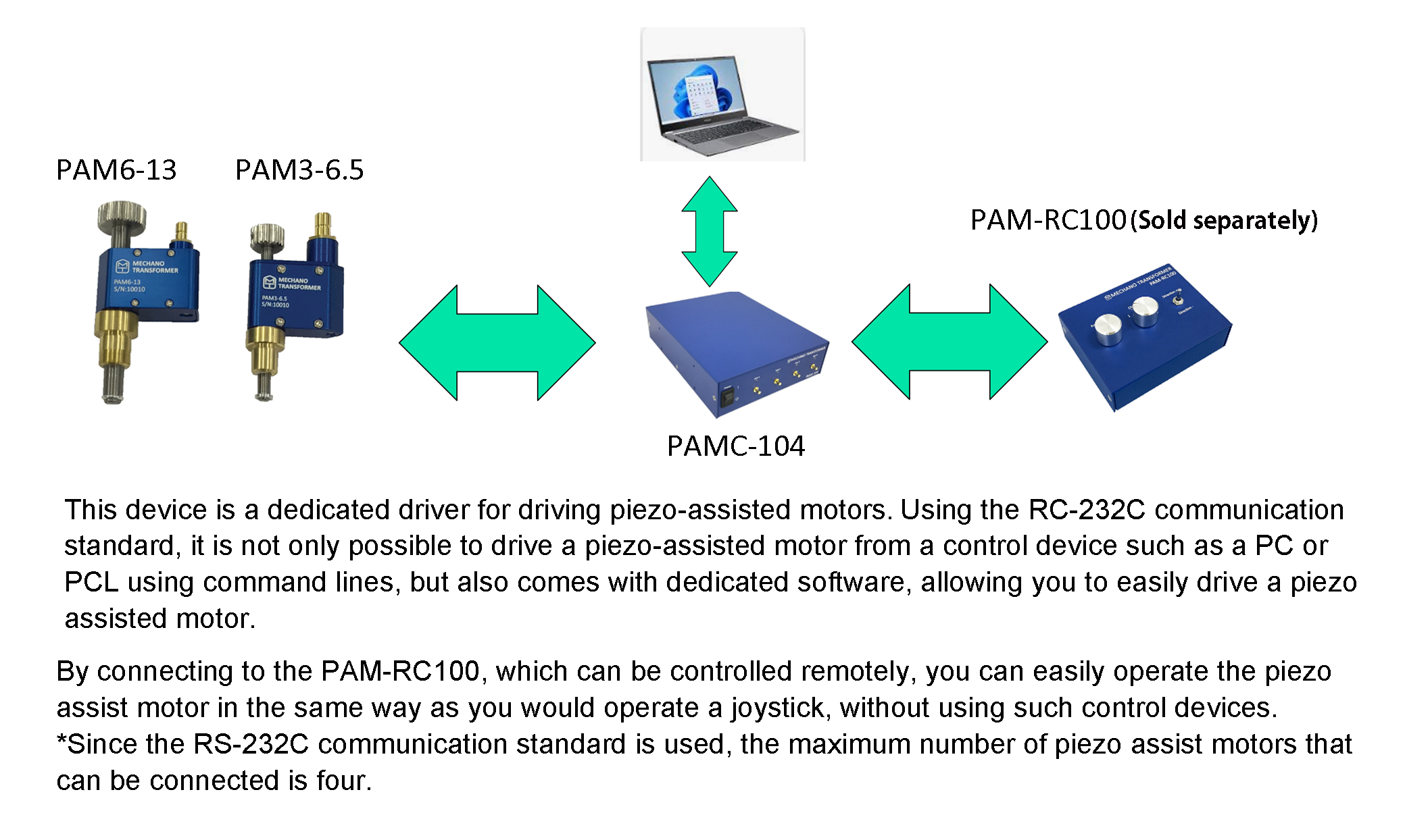
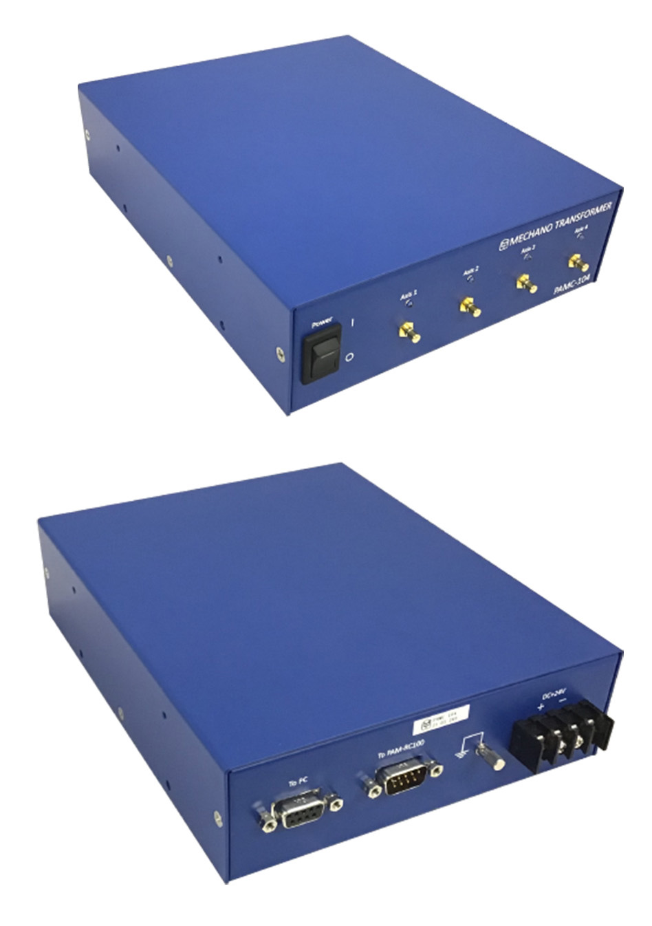
2. PAMC-104 (Please Download the software here link)
| Product | PAMC-104 |
|---|---|
| Number of Driving Axis | 4 |
| Maximum Driving Frequency (Hz) | 1500 |
| Interface | RS232C |
| Power Supply Voltage (V) | DC24 |
| Current consumption (A) | ― |
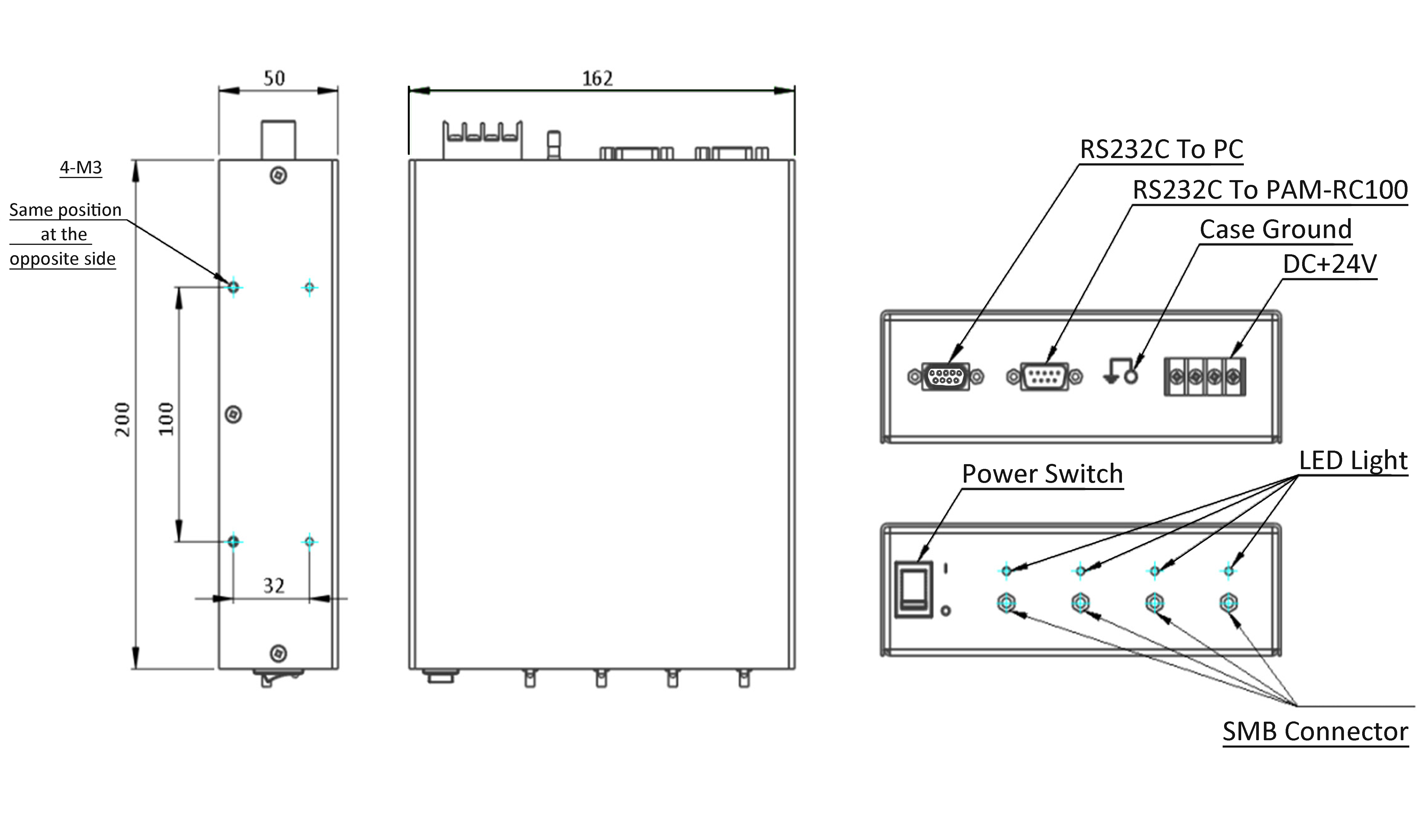
| Dimension (mm)(excluding protrusions) | 200x162x50 |
| Operating Temperature | 0~40℃ |
| Storage Temperature | 0~40℃ |
| Ambient Humidity | 10~80%RH (No condensation) |
| Weight (kg) | 1.2 |
| Price (Yen) | 132,000 |
| User manual | Download |
| 3D Model | Download |
PAMC-104
Product Configuration
| PAMC-104 | Serial number | Quantity |
|---|---|---|
| Body | PAMC-104 | 1 |
| Software installation CD | PAM-SOFT-231213-001 | 1 |
| user's manual | PAM-DOC-MAN-231213-001 | 1 |
| Attached communication cable | PAM-CA-USB-DSUB9-1 | 1 |
Product Configuration
| Serial number | Quantity | |
|---|---|---|
| (Sold separately) Power adapter | UNI345-2419-PL03B | 1 |
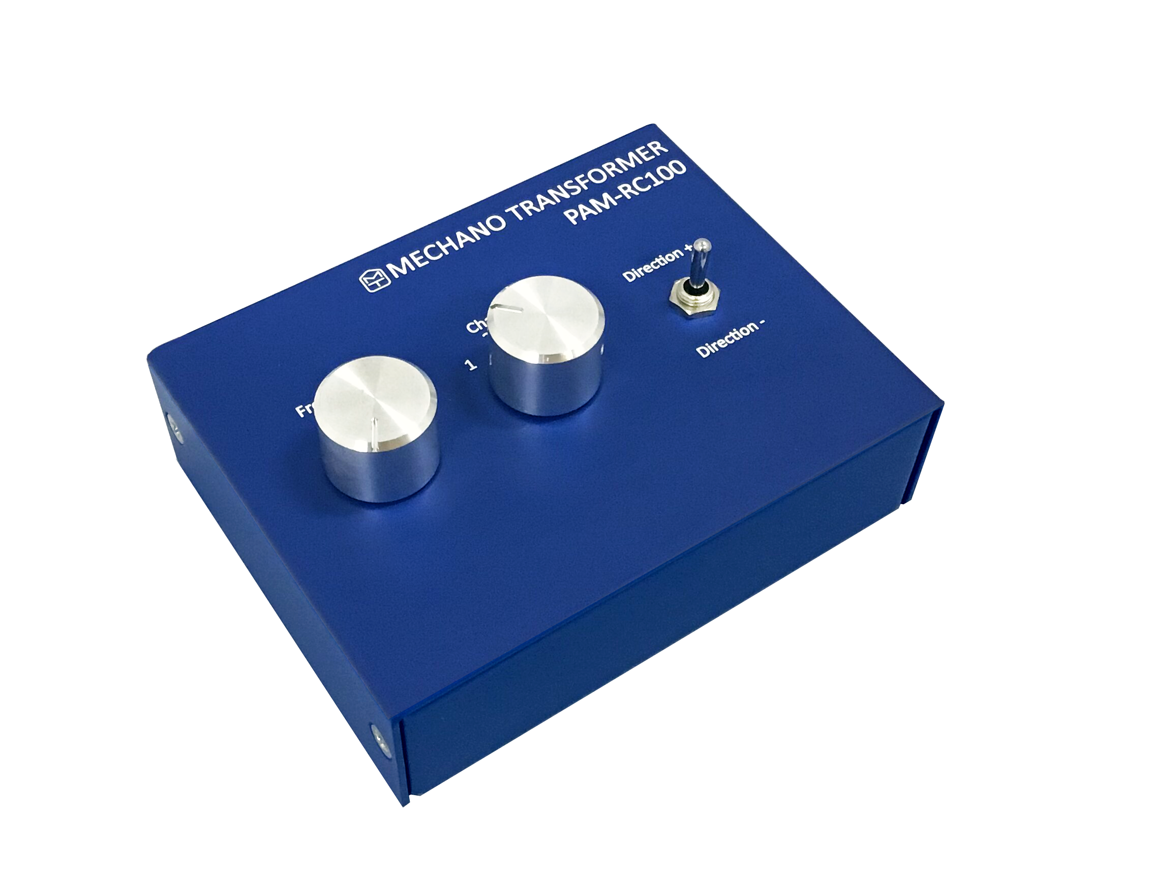
4. PAM-RC100
| Product | PAM-RC100 |
|---|---|
| Driving Frequency (Hz) | 1500 |
| Switchable channel number | 4 |
| Interface | RS232C |
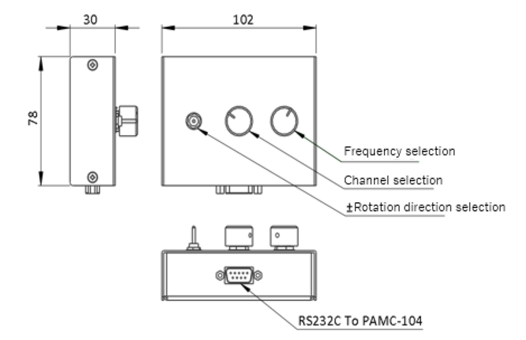
| Dimension (mm)(excluding protrusions) | 102x78x30 |
| Operating Temperature | 0~40℃ |
| Storage Temperature | 0~40℃ |
| Ambient Humidity | 10~80%RH(No condensation) |
| Weight (kg) | 0.32 |
| Prices (Yen) | 55,000 |
| User manual | Download |
PAM-RC100(Sold separately)
Product Configuration
| PAM-RC100 | Serial number | Quantity |
|---|---|---|
| Body | PAM-RC100 | 1 |
| Attached cable | PAM-CA-DSUB9-DSUB9-2 | 1 |
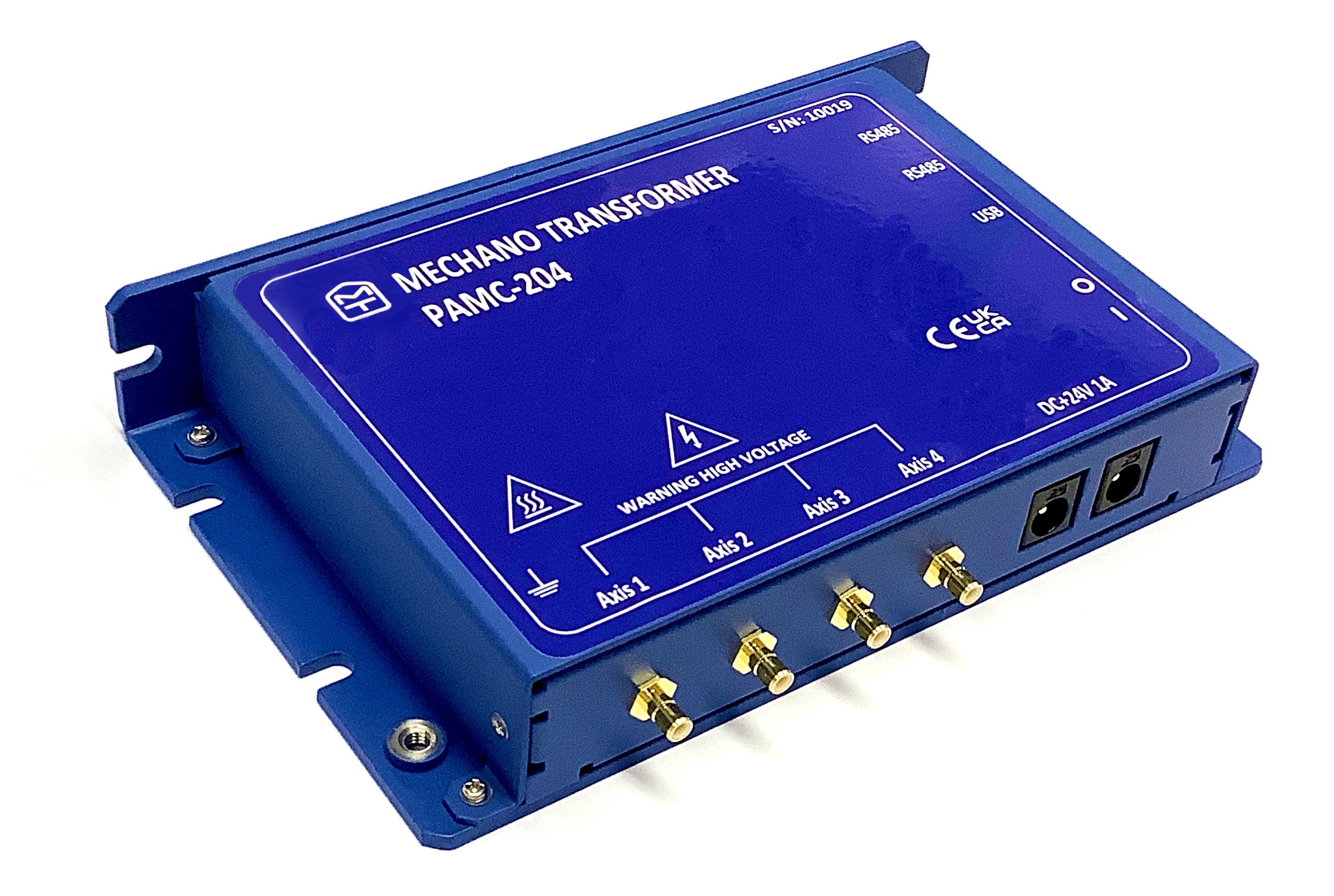
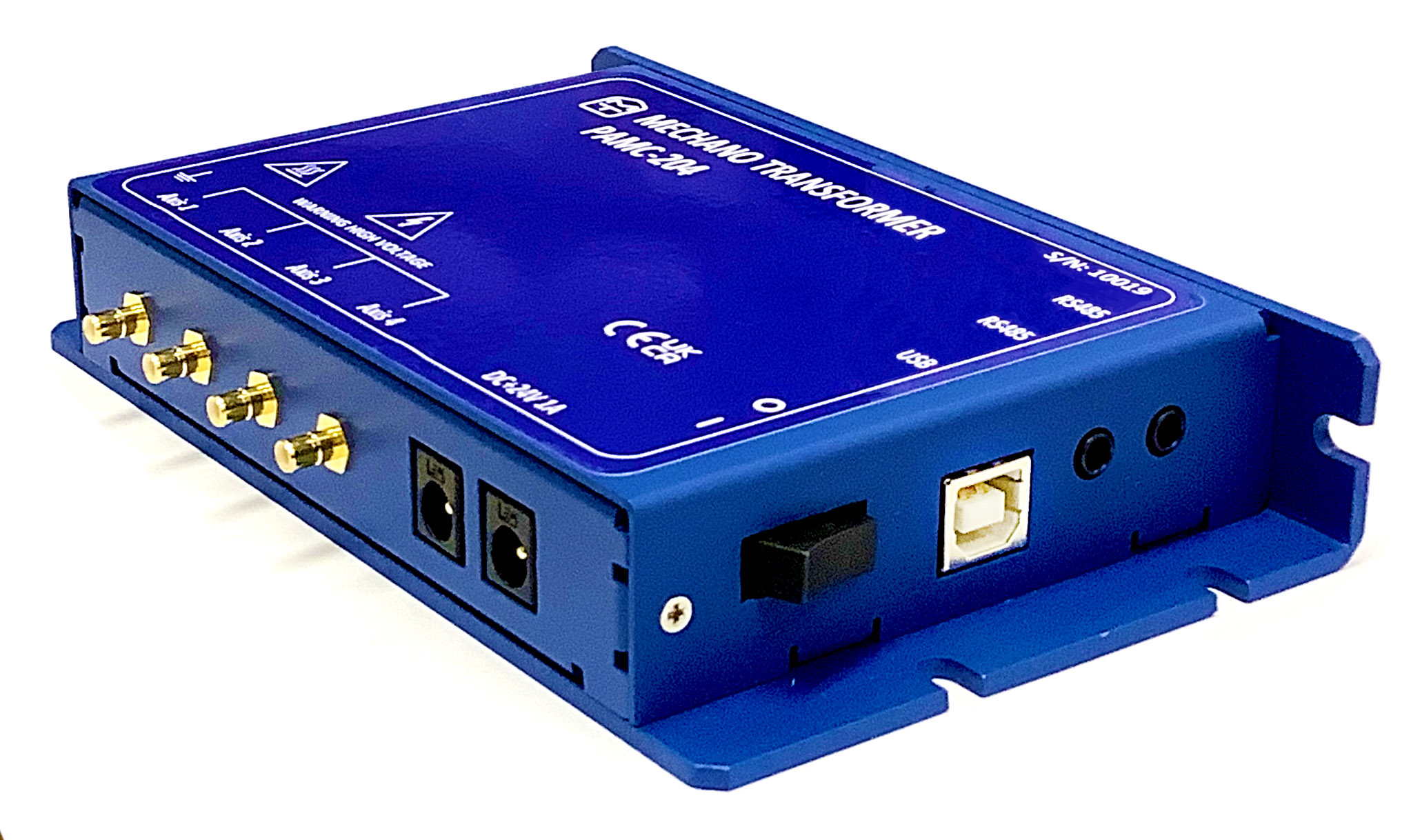
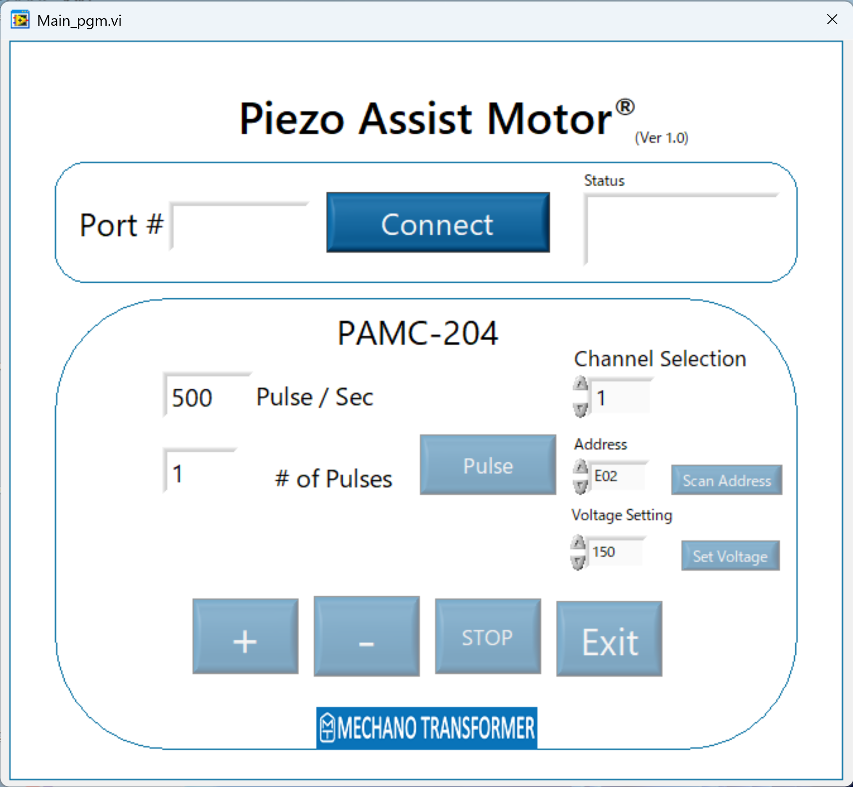
3. PAMC-204 (USB, RS485) (Please Download the software here link)
| Product | PAMC-204 |
|---|---|
| Maximum Drive Frequency(Hz) | 1500 |
| Number of Control Axes | 4 |
| Number of channel switches | 70~150* output voltage adjustable by command |
| Interface | USB, RS485 |
| Power supply voltage(V) | DC24 |
| Current Consumption(A) | 0.5A above |
| Dimension (cm)(excluding protrusions) | 148.3x91.7x26.8 |
| Operating temperature | 5~40℃ |
| Storage temperature | 5~40℃ |
| Ambient Humidity | 10~80%RH (No condensation) |
| Weight (kg) | 0.35 |
| Price (円) | 176,000 |
| User manual | Download |
| 3D Model | Download |
PAMC-204
Piezo Assist MotorⓇ Nanometer level alignment
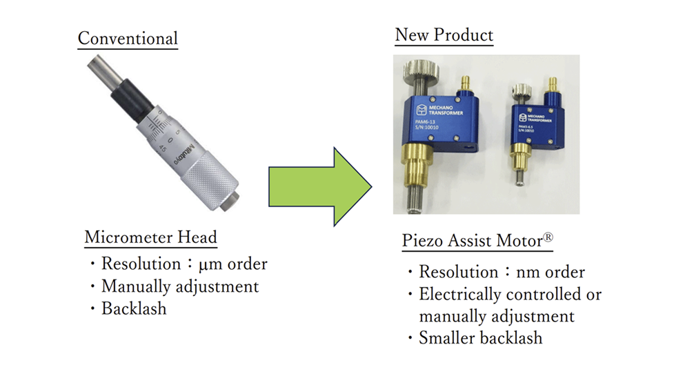
Make your manual stage to nanometer positioning stage
Details:
By just replace the micrometer head with the Piezo Assist MotorⓇ, the manual stage is transform to:
The merits of using Piezo Assist MotorⓇ
⇒Turn your manual stage to nanometer order positioning stage and electrically controlled precision stage
Piezo Assist MotorⓇ is a piezoelectric driven actuator with a resolution of less than 30 nanometers. Manual stage can be transformed into nanometer order positioning stage and electrically controlled precision stage.
Example
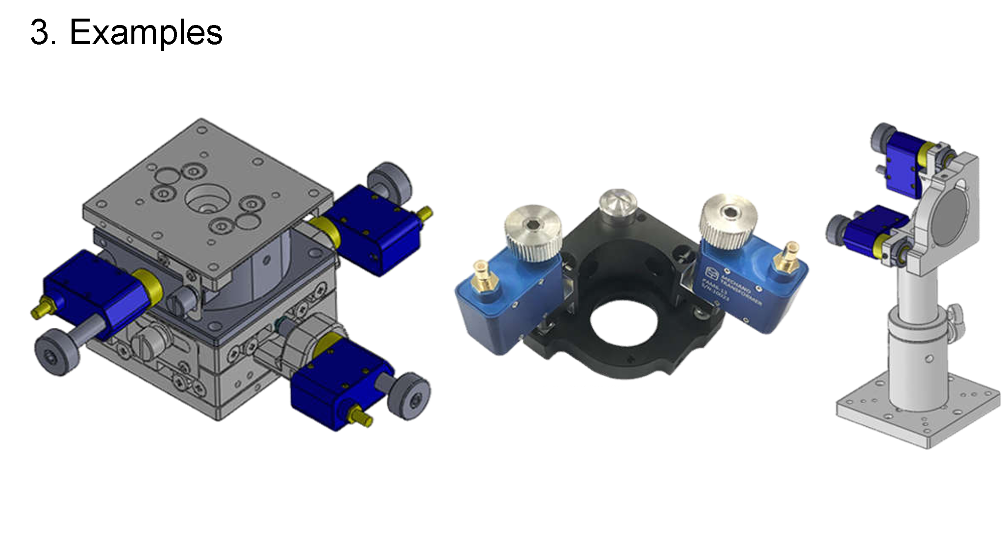
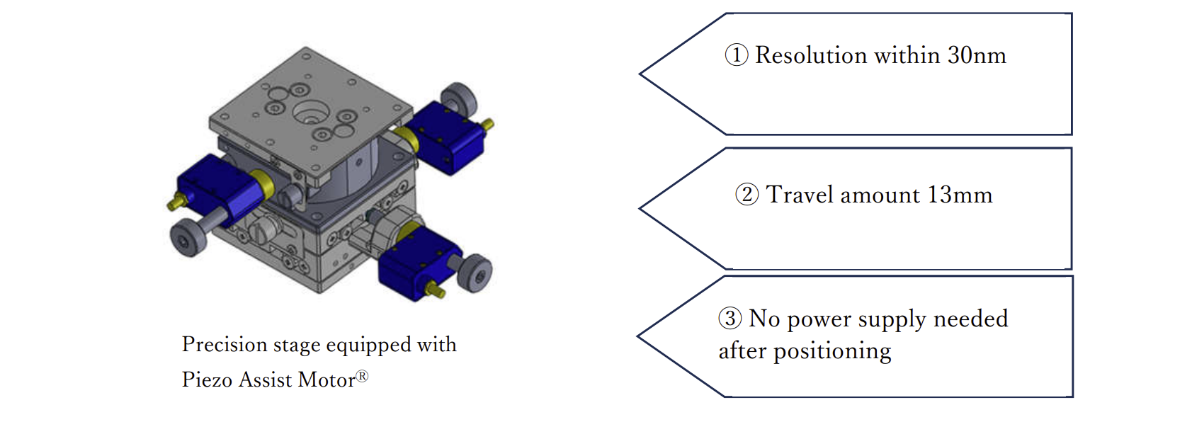
1. Transform your manual stage to precision stage
3-axis manual stage equipped with Piezo Assist MotorⓇ
Example:Micromanipulator、Scanning microscope、High resolution microscope etc.
2.Mirror Mount
2-axis mirror mounter with Piezo Assist MotorⓇ
Examples: Interferometer construction, Laser irradiation positioning, Laser welding etc.
Some examples applications & video
Active Laser Beam Stabilization Systems
PAM LOAD 3KG
Operating precautions:
1. A high voltage is applied to the Piezo Assist MotorⓇ during operation. Use only specified controllers such as PAMC-104 or PAMC-204 to drive the motor.
2. If you need to disconnect or plug in the cable from the Piezo Assist MotorⓇ or controller, turn off the power to the controller before doing so.
3. Do not disassemble or modify the piezo assist motor or controller PAMC-104 or PAMC-204.
4. Do not use the motor near flammable materials or damp or humid areas.
5. If a strange odor, noise, overheating, or heat radiation is detected, please turn off the controller and check the situation.
6. Do not turn on the driver after dropping the controller or subjecting it to impact.
7. Do not touch the PAM during operation, as high voltages are applied during operation.
8. If the Piezo Assist MotorⓇ moves to the threaded end, you can manually adjust the position by turning the adjustment knob.
9. Piezo Assist MotorⓇ is an open loop device. If absolute position is required, a seperate external sensor must be provided, and a closed loop must be configured.
10. During operation, the Piezo Assist MotorⓇ produces high pitch noise.
11. You can prevent grease from sticking by moving the knob from one end to the other to redistribute the grease from time to time. If the motor is not used for a long time, the grease may become hard. In that case, you may be able to fix it by manually turning the knob from one end to the other.
Download
.png)
Piezo Assist Motor Pamphlet ver4
You can download a brochure summarizing the product features, application examples, and technical specifications of the Piezo Assist Motor®.
・Pamphlet (PDF : 2.3MB)

Nano Aligment Stage Series
 .png)
MTPAM-TSD-402SR (XY axis stage)
・Datasheet (PDF : 463KB)
・3D Model
(STEP file : 5.5MB)

MTPAM-TSD-602SR
・Datasheet (PDF : 488KB)
・3D Model
(STEP file : 5.5MB)
.png)
MTPAM-TSD-603
・Datasheet (PDF :426KB)
・3D Model
(STEP file : 5.5MB)
Nano Aligment Mirror Mount Series
MTPAM-LMHB 30M
・Datasheet (PDF : 463KB)
・3D Model
(STEP file : 5.5MB)
MTPAM-MHG-MP30-NL
・Datasheet (PDF : 488KB)
・3D Model
(STEP file : 5.5MB)
Controllers
PAMC-104
PAM-RC100
・Datasheet (PDF : 2.09MB)
・3D Model
(STEP file : 5.5MB)
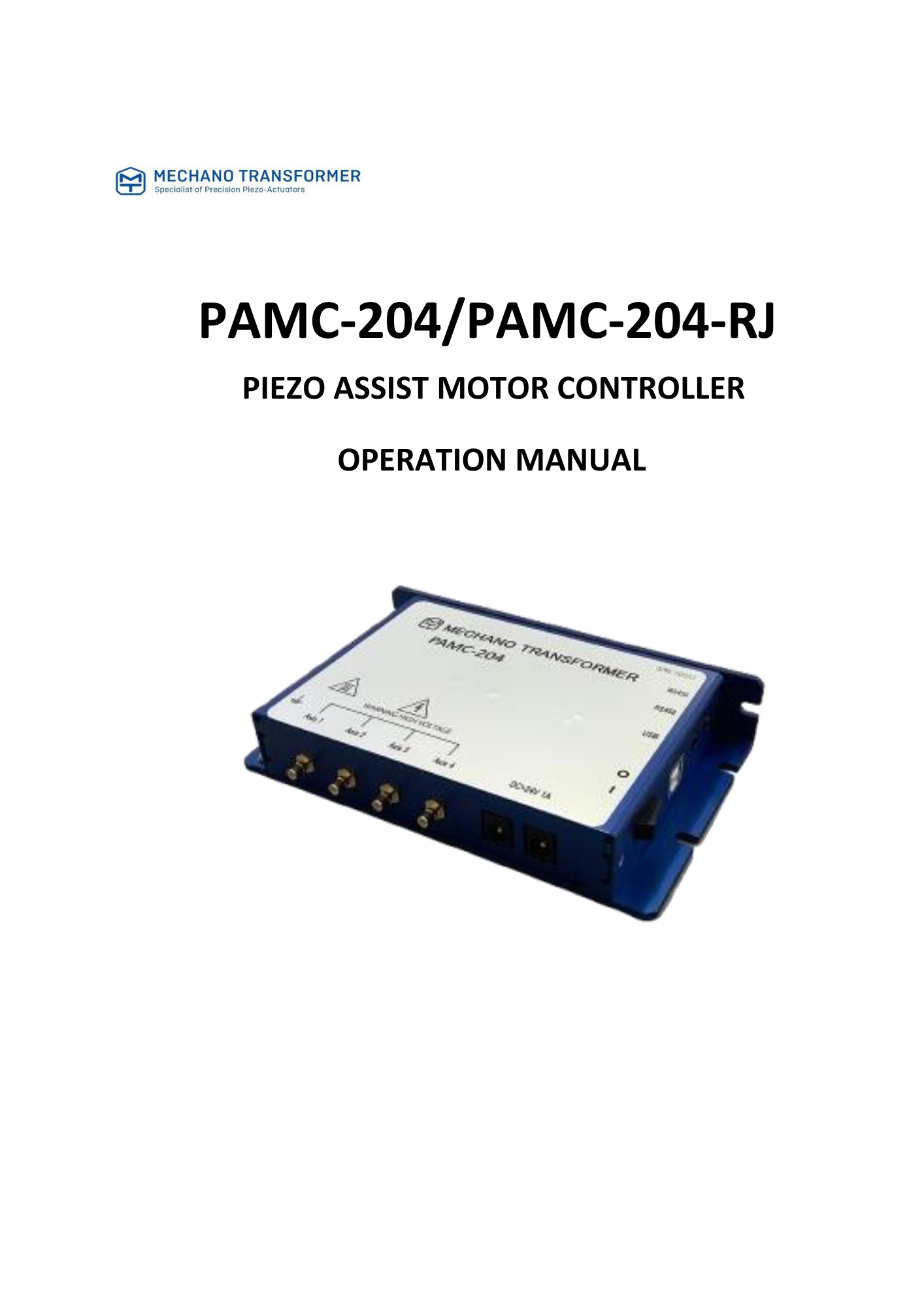
PAMC-204
PAMC-204-RJ
・Operating Instructions (PDF : 2.12MB)
・3D Model
(STEP file : 5.5MB)
Software
PAMC-204
・Software

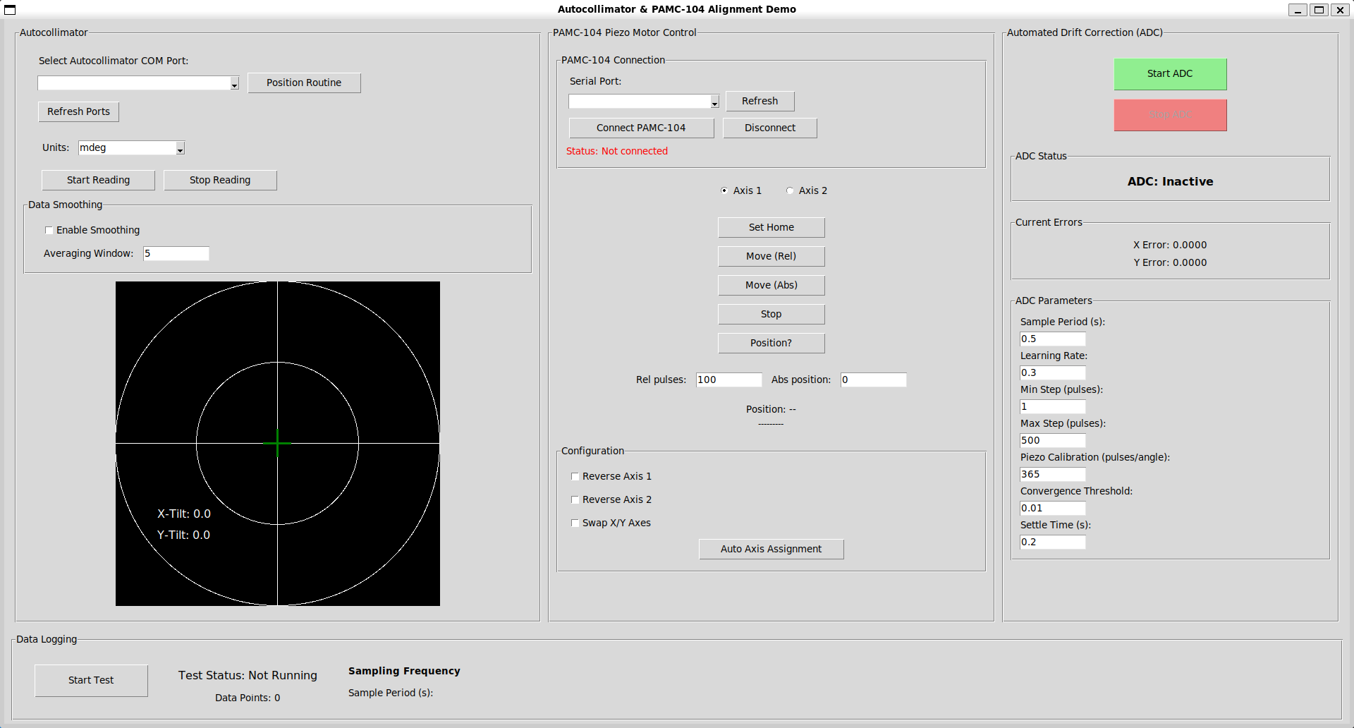
Autocollimator
・Python