



TECHNOLOGY
MechaTrans®
1. Displacement and generated force
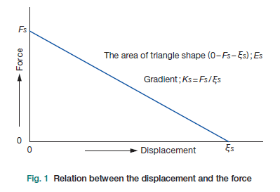
Figure 1 shows how displacement and generated force relate to each other. The displacement ξs at the mechanical output point is measured with the recommended 100 V applied and no external load, that is, in the free condition. The force Fs is generated when 100 V is applied and the output point is held fixed. The gradient of the line, Ks = Fs / ξs, represents the rigidity of MechaTrans®, and the area of the triangle 0 – Es – ξs is the energy Es that MechaTrans® itself produces.
2. Behaviour under static load
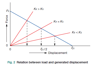
Figure 2 shows the displacement produced under a static load such as a spring.
If the load rigidity Kx equals the rigidity Ks of MechaTrans®, the displacement is half of the free condition. A larger Kx gives less than half, and a smaller Kx gives more than half.
The energy delivered to the load is greatest when Kx equals Ks, and at that point it is a quarter of the total energy of MechaTrans® shown in figure 1.
3. Performance under dynamic load
The loading mass M and the rigidity of MechaTrans® together form a mechanical resonance system, and the resonance frequency follows from the equation shown.
M matters a great deal here. It is the mass at the output point of MechaTrans® plus the mass of the load. When a step voltage is applied, the maximum kinetic energy transferred to M during the transient equals the energy of the piezoelectric device itself, so the difference between dynamic and static conditions is far from negligible.
Please consult us before running MechaTrans® under dynamic conditions. Without the right precautions the actuator can be damaged.
Operating precautions: do not superimpose DC voltage instantaneously →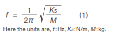
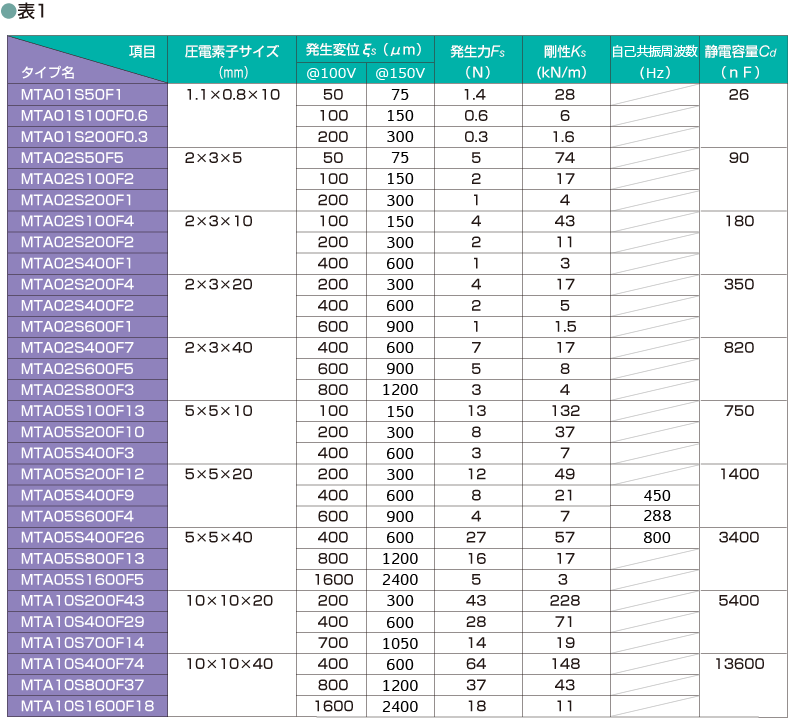
Standard MechaTrans® products
Every series below is a standard product, and we can adapt any of them to your requirements.
Need help sizing an actuator?
Send us your load, displacement and drive frequency and we will work through the numbers with you.
CONTACT US →